|
Hardness Testing Machine | | | | | | | | | SAROJ make Brinell Hardness Testing Machine | | | Universal Testing Machine | | | | | | | |
|
|
|
 |
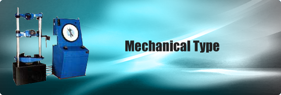
Mechanical Type |
|
| |
 |
|
|
Loading Accuracy as high as + 1%
|
| Straining at variable speeds to suit a wide range of materials. |
Continuous roll autographic recorder supplied as standard to enable study of the
behavior of materials
|
Motor driven threaded columns for quick effortless adjustment of lower cross-head-to
facilitate rapid fixing of test specimen.
|
| High reading accuracy due to large size and design of dial. |
| Wide range of standard and special accessories, including load stabilizer. |
| Easy change from plain to threaded and screwed specimens. |
|
|
Large effective clearance between columns enables testing of standards specimens as well as
structures.
|
| Simple controls for easy of operation. |
Robust staining frame of an extremely rigid construction.
|
Safe operation ensured be means of safety devices.
|
| Fully enclosed and protected pendulum. |
| |
Application :
|
| |
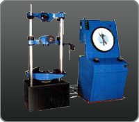
| FIE Universal Testing Machine is designed for testing metals and other materials under tension, compression bending, transverse and shear loads. Hardness test on metals can also be conducted. |
| |
Principal of Operation :
|
| |
| Operation of the machines is by hydraulic transmission of load from the test specimen to a separately housed load indicator. The hydraulic system is ideal since it replaces transmission of load through levers and knife edges, which are prone to wear and damage due to shock on rupture of test pieces. |
| |
| Load is applied by a hydrostatically lubricated ram. Main cylinder pressure is transmitted to the cylinder of the pendulum dynamometer system housed in the control panel. The cylinder of the dynamometer is also of self-lubricating design. The load transmitted to the cylinder of the dynamometer is transferred through a lever system to a pendulum. Displacement of the pendulum actuates the rack and pinion mechanism which operates the load indicator pointer and the autographic recorder. The deflection of the pendulum represent the absolute load applied on the test specimen. |
| |
| Return movement of the pendulum is effectively damped to absorb energy in the event of sudden breakage of a specimen. |
| |
| Machine consists of : |
| |
Straining Unit
|
| |
| This consists of a hydraulic cylinder motor with chain and sprocket drive and a table coupled with the ram of the hydraulic cylinder, mounted on to a robust base. The cylinder and the ram are individually lapped to eliminate friction. The upper cross-head is connected to two screwed columns which are driven by a motor. Axial loading of the ram is ensured be reveling the cylinder and ram of of any possible side loading by the provision of ball seatings. |
| |
| An elongation scale with a minimum graduation of 1 mm, is provided to measure the deformation of the specimen. |
| |
| Tension test is conducted by gripping the test specimen between the upper and lower cross-heads, |
| |
Compression, transverse, bending, shear and hardness tests are conducted between the lower cross head and the table.
|
| |
| The lower cross-head can be raised or lowered rapidly by operating the screwed columns thus facilitating ease of fixing of the test specimen. |
| |
Control Panel :
|
| |
| The control Panel consists of a power pack complete with drive motor and an oil tank, control valves a pendulum dynamometer a load indicator system and an autographic recorder. |
| |
| Power Pack : |
| |
| The power pack generates the maximum pressure of 200 kgf/cm2 the hydraulic pump provides continuously non-pulsating oil flow. Hence the load application is very smooth. |
| |
Hydraulic Controls :
|
| |
| Hand operates wheels are used to control the flow to and from the hydraulic cylinder. The regulation of oil flow is infinitely variable incorporated in the hydraulic system is a regulating valve which maintains a practically constant rate of piston movement. Control by this valve allows extensometer readings to be taken. |
| |
Load Indicator System :
|
| |
| This system consists of a large dial and a pointer. A dummy pointer is provided to register the maximum load reached during the test. Different measuring ranges can be selected by operating the range selection knob. An overload trip switch is incorporated which automatically cuts out the pump motor when the load range in use is exceeded. |
| |
Pendulum Dynamometer :
|
| |
| This unit permits selection of favorable hydraulic ratios producing relatively small frictional forces. Pressurised oil in the loading cylinder pushes up the measuring piston proportionately and actuates the special dynamometer system. The piston is constantly rotated to eliminate friction. The dynamometer system is also provided with an integral damper and ensures high reliability of operation. The load transmitted to the dynamometer is transferred through a pendulum to the load indicator. |
| |
Autographic Continuous Roll Load-Elongation Recorder :
|
| |
| This unit is of the pen and drum type and is supplied as standard. The horizontal motion of the pen produces the load ordinate of the diagram and the drum rotation produces the extension ordinates in the ration of either 1:5 or 1:10. |
| |
| Accuracy & Calibration : |
| |
| AII FIE Universal Testing Machines are closely controlled for sensitivity, accuracy and calibration during every stage of manufacture. Every machine is then calibrated over each of its measuring ranges in accordance with the procedure laid down in BS : 1610 : Part 1 :1992 and IS 1828 : (Part 1) : 1991. |
| |
FIE Universal Testing Machines comply with Grade "A" of BS : 1610 : Part 1:1992 and class 1 of IS 1828 : (Part1) : 1991
An accuracy of + 1.0% is guaranteed from 20% from 20% of the load range selected to full load. Below 20% of the selected range, the maximum permissible error is 0.2% of the full load reading. |
| |
| SPECIFICATION : |
| |
| MODEL |
- |
UTN-10 |
UTN-20 |
UTN-40 |
UTN-60 |
UTN-100 |
UTN-200 |
UTN-300 |
| Maximum capacity |
kN |
100 |
200 |
400 |
600 |
1000 |
2000 |
3000 |
| 1st Measuring Range |
kN |
0-100 |
0-200 |
0-400 |
0-600 |
0-1000 |
0-2000 |
0-3000 |
| Minimum Graduations |
kN |
0.2 |
0.4 |
1 |
1 |
2 |
4 |
5 |
| 2nd Measuring Range |
kN |
0.50 |
0-100 |
0-200 |
0-300 |
0-500 |
0-1000 |
0-1500 |
| Minimum Graduations |
kN |
0.1 |
0.2 |
0.5 |
0.5 |
1 |
2 |
2.5 |
| 3rd Measuring Range |
kN |
0.25 |
0-50 |
0-100 |
0-120 |
0-250 |
0-500 |
0-600 |
| Minimum Graduations |
kN |
0.05 |
0.1 |
0.25 |
0.2 |
0.5 |
1 |
1 |
| 4th Measuring Range |
kN |
0.10 |
0-20 |
0-40 |
0-60 |
0-100 |
0-200 |
0-300 |
| Minimum Graduations |
kN |
0.02 |
0.04 |
0.1 |
0.1 |
0.2 |
0.4 |
0.5 |
| Clearance for tensile at fully descended working piston |
mm |
50-700 |
50-700 |
50-700 |
50-800 |
50-850 |
50-900 |
50-900 |
| Clearance for compression test at fully descended working piston |
mm |
0-700 |
0-700 |
0-700 |
0-800 |
0-850 |
0-900 |
0-900 |
| Clearance between columns |
mm |
500 |
500 |
500 |
600 |
750 |
850 |
850 |
| Ram stroke |
mm |
150 |
200 |
200 |
250 |
250 |
300 |
300 |
| Straining/piston speeds (at no load) |
mm/min |
0-300 |
0-150 |
0-150 |
0-100 |
0-80 |
0-45 |
0-50 |
| CONNECTED LOAD |
- |
- |
- |
- |
- |
- |
- |
- |
| HP |
- |
1.3 |
1.3 |
2.3 |
2.5 |
3.5 |
6.5 |
8.5 |
| V |
- |
400-440 |
400-440 |
400-440 |
400-440 |
400-440 |
400-440 |
400-440 |
| Æ |
- |
3 |
3 |
3 |
3 |
3 |
3 |
3 |
| DIMENSIONS |
- |
- |
- |
- |
- |
- |
- |
- |
| L X W X H (approx.) |
mm |
2032 x
750 x
1960 x |
2032 x
750 x
1960 x |
2060 x
750 x
2180 x |
2065 x
750 x
2534 x |
2415 x
815 x
2900 x |
3000 x
1200 x
3600 x |
3500 x
1900 x
4550 x |
| Weight approx. |
kg |
1500 |
1500 |
2500 |
3500 |
5500 |
12 500 |
22 000 |
| STANDARD ACCESSORIES |
- |
- |
- |
- |
- |
- |
- |
- |
| FOR TENSION TEST |
- |
- |
- |
- |
- |
- |
- |
- |
| Clampings jaws for flat specimens diameter |
mm |
10-20
20-30 |
10-20
20-30 |
10-25
25-40 |
10-25
25-40
40-55 |
10-25
25-45
45-70 |
20-40
20-60
60-80 |
25-50
50-70
70-90 |
Clampings jaws for flat specimens thickness
width |
mm |
0-10
10-20
50 |
0-10
10-20
50 |
0-15
15-30
65 |
0-15
15-30
70 |
0-22
22-44
44-65
70 |
0-20
20-45
45-70
90 |
0-25
25-50
50-75
100 |
| FOE COMPRESSION TEST |
mm |
- |
- |
- |
- |
- |
- |
- |
| Pair of compression plates of diameter |
mm |
120 |
120 |
120 |
120 |
160 |
220 |
220 |
| FOR TRANSVERSE TEST |
mm |
- |
- |
- |
- |
- |
- |
- |
| Table with adjustable rollers width of rollers |
mm |
160 |
160 |
160 |
160 |
160 |
200 |
200 |
| Diameter of rollers |
mm |
30 |
30 |
30 |
50 |
50 |
70 |
70 |
| Maximum clearance between supports |
mm |
500 |
500 |
500 |
600 |
800 |
900 |
1000 |
| Radius of punch tops |
mm |
6,12 |
6,12 |
12, 16 |
16, 22 |
16, 22 |
30, 40 |
50, 75 |
|
| |
Special Accessories :
|
|
|
Installation : |
| These include load stabilizer, Brinell test Attachment, Bend Test Attachment, Shear Test Attachment and a wide range accessories offered on request at additional cost. |
|
|
It is recommended that machines be erected on a foundation. Details on foundation can be given on request |
|
| |