Loading...
 
Hardness Testing Machine | Rockwell Hardness Testing Machine | Vickers Hardness Tester [Model VM-50] | Computerised Hardness Tester [Model : VM 50 PC] | Computerised Brinell Hardness Tester [Model : B3000 PC] | Computerised Brinell Image Analysis System [B.I.A.S] | Computerised Fully Automatic Brinell Hardness Testing Machine [Model -B3000PCFA] | Portable Hardness Tester [ Model - PR 1] | SAROJ make Rockwell Hardness Testing Machine | SAROJ make Brinell Hardness Testing Machine | Brinell Hardness Tester Model B 3000 [O] | Brinell Hardness Tester Model B 3000 [H] | Universal Testing Machine | Mechanical Type | Electronic Type | Electro-Mechanical Universal Testing Machines | Model Unitek 9400 Series | Model Unitek 9700 Series | Electro-Mechanical PC Control Universal Testing Machine | Unitek 9500 Series | Impact Testing Machine
Portable Hardness Tester [ Model - PR 1]
 
'DT' portable Rockwell Hardness Tester is developed to meet the demands of a light weight instrument which can be used to carry out by a universally recognised method of hardness testing.

Rockwell Method :
This hardness tester can be used in variety of applications and is readily adjustable to a wide range of sizes and shapes which are difficult to test in a standard table model hardness tester.
The machione os designed for carrying out Rockwell tests comparable to table model hardness tester because, the basic things, such as shape of penetration, measurement and loads are same in both systems.

 
The photograph on the back side gives the general arrangement of the hardness tester.
The system carries a weight bar (8) pivoted at central point. When the load is applied by the loading screw (9), at one end of this weigh bar, it is deflected and theother end of this bar carrying penetrator forces down into the testspecimen. This deflection of weight bar which is proportional to the applied load is indication of the loading dial indicator (11). Besides this loading dial indicator, there is one penetration measuring indicator(14) which masures the actual penetration of the penterator into the test specimen. The hardness value of the specimen is read directly on this indicator.
 
The frame carries two adjusting screws and gear train. By roating the knurled knob the distance between the penetrator and the support-anvil can be adjusted.
 
1)  Upper clamp
2)  Lower clamp
3)  Support anvil
4)  Adjusting screws
5)  Knurled Knob
6)  penetrator
7)  Penetrator tightening screw
8)  Weight bar
9)   Loading Screw
10) Handle
11) Loading dial indicator
12) Indocator seat support
13) Indicator seat
14) Penetration measuring indicator
Method of Test
 
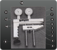
1) Select proper penetrator (6) depending upon the material to be tested.
2) Take precaution so thet the penetrator does not project beyond the Upper clamp(1).  For this, the loading screw (9) should be sufficiently taken back.
3) place the test specimen securely on suitable anvil(3).
4) Clamp test specimen firmly between upper clamp (1) and support anvil (3) by rotating the knurled knob (5) on the lower clamp (2). DO NOT APPLY EXTRA PRESSURE.
5) CHECK ZERO SETTING LOAD INDICATOR (11). Rotate bezel to bring pointer over small black dot for zero load..
6) Apply 10 kgf (98.07 N). major load screw (9) in clockwise direction such that the pointer on the load indentor (11) comes on set position.
7) Check zero setting of penetrator indicator (14). Rotate bezel to bring pointer to ‘O’ on the black scale.
8) For ‘C’ scale use diamond penetrator against load of 150 kgf (1471 N) and for ‘A’  scale use same diamond penetrator against a load of 60 kgf (588.4 N). For ‘B’ scale  use 1/16 ball penetrator against a load of 100 kgf (980.7 N).
9) Take off major load by turning the loading screw in anticlockwise direction, such that only minor load of 10 kgf. (98.07) remains in action – (pointer back to ‘set’ position).
10) Hardness value in Rockwell scale is directly indicated on the penetrator indicator  (14). Read of number on black scale is diamond penetrator. Read off number on red scale is ball penetrator
11) Release load completely by taking back the loading screw (9).
12) Turn the knurled knob (5) in anticlockwise direction to loosen clamp and thus the test speciman.
 
 Maximum test height  110 mm
 Throat capacity  55 mm
 1) Flat Anvil  1 No.
 2) 'V' Anvil  1 No.
 3) Test Blocks  2 Nos.
 4) 1/16" Ball penetrator  1 No.